09. 17, 2026
How to Choose a CNC Machining Center Based on Your Workpiece
A CNC machining center should be selected around the parts it must produce.
Buyers who begin with a model name or advertised specification often discover later that the table is difficult to fixture,
the spindle is poorly matched to the tooling, or too many setups are needed to hold tolerance.
A workpiece-based selection process reduces these risks and creates a clearer basis for comparing quotations.
Start with the Workpiece Envelope
List the raw blank dimensions and finished dimensions for every representative part.
The blank matters because it is what must fit inside the machine before material is removed.
Add the fixture, clamps, parallels, rotary table or tombstone to calculate the complete setup envelope.
Machine travel must cover more than the nominal part size.
The cutter needs access around edges, and the spindle head needs clearance above clamps and fixtures.
Check X, Y and Z travel together with table dimensions, the distance from spindle nose to table and the distance from spindle centerline to the column or other enclosure limits.
Avoid selecting a machine whose travel only just equals the drawing dimensions.
A small margin can disappear when a vise, fixture plate or long tool is added.
At the same time, buying a much larger machine than required may increase floor-space, tooling and operating costs.
The correct size provides safe access for the real setup and reasonable flexibility for future parts.
Workpiece weight must include the fixture. Compare that total with the permitted table load for the exact machine.
Load distribution also matters: a long or irregular casting may place weight away from the table center.
Ask the supplier to review the setup when the load is concentrated or approaches the machine limit.
Let Part Geometry Guide Machine Orientation
A vertical machining center range is often suitable for plates, mold components, fixtures, brackets, covers and prismatic parts that can be machined mainly from the top.
The vertical spindle gives the operator a clear view of the setup and supports familiar vise and fixture arrangements. It is a flexible choice for job shops and mixed production.
Horizontal machining centers can be considered for box-type parts, housings and components requiring machining on several sides.
A horizontal layout may improve access to side faces and help chips fall away from the cutting zone.
Pallet and tombstone arrangements can support repeated production, but the fixture plan and required operations must justify the investment.
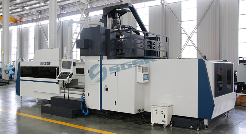
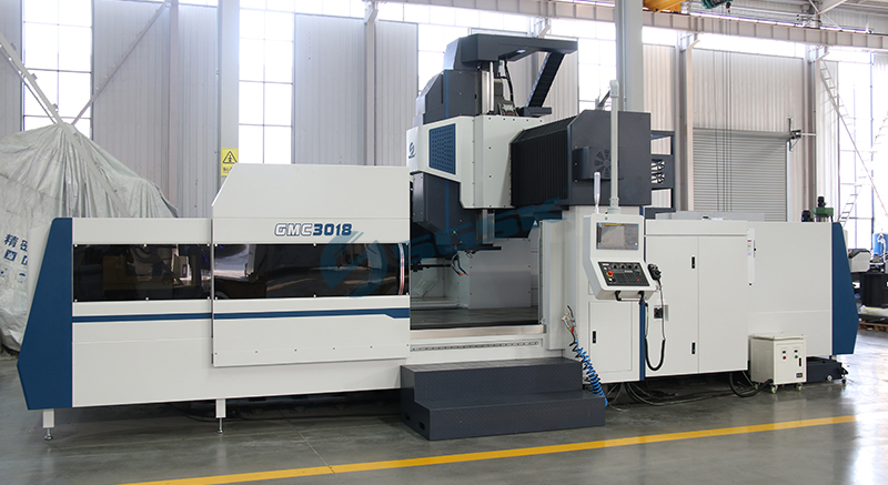
Gantry machining centers are intended for large plates, frames, bases, molds and other workpieces that require a broad working area and structural support.
Buyers should examine clearances between the columns and under the crossbeam, not just nominal axis travel.
5-axis CNC machining centers become relevant when complex surfaces, angled holes or multiple faces must be reached with fewer setups.
Five-axis capability can improve access and reduce reclamping, but it should be chosen because the part geometry and process require it—not simply because it is more advanced.
Match the Spindle to Material and Tooling
The spindle should be chosen after reviewing workpiece material, cutter diameter, tool length and material-removal strategy.
Aluminum components may use smaller tools and higher spindle speeds, while large steel or cast-iron parts may demand greater torque and structural rigidity.
These are general tendencies, not fixed rules.
Prepare a tool list for the important operations. Include face mills, end mills, drills, taps, boring tools and any long-reach cutters.
Tool taper, spindle speed range, motor characteristics and tool-retention capacity must suit this list.
A machine that reaches a high maximum speed may still be poorly matched if the process needs torque at a lower operating speed.
Translate Features into Axis and Setup Requirements
Mark every machined face, hole, pocket, thread and contour on the drawing.
Then group them by setup.
A simple top-and-bottom plate may need two setups on a vertical machine.
A housing with features on four sides may justify a rotary table or horizontal machining center.
A complex impeller or angled manifold may require simultaneous or indexed multi-axis motion.
The objective is not always to eliminate every setup.
Additional axes add programming, tooling and maintenance considerations.
The best process is the one that achieves the required quality and output with manageable complexity.
Compare alternatives using expected setup time, in-process inspection, fixture cost and operator skill—not only cutting time.
For a rotary axis, confirm load, center height, clamping method and available machine space.
An optional fourth axis changes the usable envelope and may reduce table area.
It should never be assumed to be standard merely because another model page shows one.
Define Accuracy and Surface Requirements Carefully
Terms such as “high precision” are too broad for machine selection.
Identify the specific dimensional tolerances, positional tolerances, flatness, perpendicularity and surface-finish requirements on the part.
Separate features controlled within one setup from relationships that must be maintained across multiple setups.
If tolerance is critical, provide the drawing rather than a verbal summary.
A supplier can then evaluate whether the machine class is appropriate and whether process changes, inspection equipment or environmental controls should be considered.
Select Guideways for the Cutting Duty
Guideway selection should follow the required balance of axis speed, load capacity, vibration damping and maintenance.
Linear guideways are commonly used where responsive motion and efficient rapid travel are valued.
Sliding or hardened guideway designs are often considered for demanding cutting loads and damping. Hybrid arrangements may also exist.
No guideway label guarantees a result by itself. Size, preload, lubrication, machine mass and structural design all contribute.
Evaluate the proposed guideway system with the workpiece material, cutter engagement and duty cycle.
For a deeper comparison, see the site’s article on linear guides and hard rails, while confirming current specifications directly for the model under consideration.
Calculate Tool Capacity from the Process
Magazine station count is only one factor.
Check maximum tool weight, length and diameter, as well as restrictions for oversized tools.
Tool-change arrangement and actual change sequence can affect non-cutting time.
Because magazine details differ by model and option, use the final quotation and technical sheet as the controlling documents.
Consider Volume, Automation and Regional Conditions
For prototypes and varied small batches, flexibility and easy setup may be more valuable than specialized automation.
For repeated batches, pallet systems, probing, chip conveyors, tool monitoring or automatic loading may improve utilization.
The decision should be based on batch size, changeover frequency, staffing and the stability of incoming orders.
Installation conditions also matter for customers across Asia, Europe, North America and South America.
Confirm electrical supply, transformer requirements, local safety expectations, ambient temperature, humidity, compressed air, floor loading, door access and service arrangements.
These items can affect the delivered configuration and commissioning plan without changing the basic machine model.
Build a Workpiece-Based Request for Quotation
A useful request for quotation should include:
2D drawings and, where available, 3D files.
Blank and finished dimensions.
Material and heat-treatment condition.
Workpiece and fixture weight.
Critical tolerances and surface requirements.
Monthly or annual production quantity.
Planned operations and preferred tools.
Current cycle time, if the part is already in production.
Required CNC control, probing or automation.
Destination country, voltage and installation constraints.
This information allows the supplier to recommend a machine category and configuration rather than simply matching one dimension.
It also helps prevent standard features from one model being confused with optional features from another.
Final Selection Principle
Choose the smallest machine that safely accommodates the complete setup,
the spindle that matches the real tooling and material,
and the machine orientation that minimizes unnecessary handling.
Add automation only where production volume and process stability support it. Finally,
compare the full technical offer—machine, options, tooling interface, installation and support—rather than comparing model names alone.
Inquiry CTA: Need help matching a machining center to your parts?
Request a machine recommendation and send GSK Equipment your workpiece drawings, material, dimensions, tolerances, operations and target output.
The team can review the application and prepare a suitable configuration and quotation without mixing specifications from unrelated models.
Previous: None
Next: CNC Pipe Threading Lathe Machine for Oil and Gas Industry Applications
Navigation
Tel.: +86 632 5083 879
Mob.: +86 151 6326 5369
Wechat: +86 151 6326 5369
E-mail: info@gskequipment.com
WhatsApp: +86 151 6326 5369